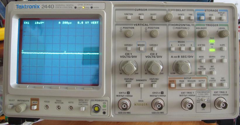
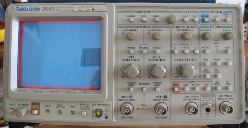
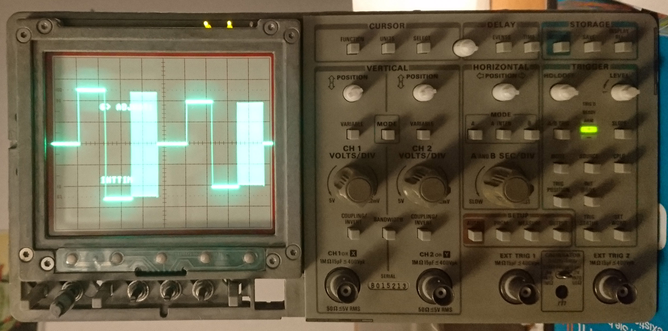
The cathode ray tube is also worth mentioning, since it is not a cheap TV tube (as in many newer scopes) where the graticule is drawn by the electron beam, but a real analog scope tube with a flat face plate and fine, etched marks on it. As many as 1024×1024 dots are displayed on the 10×10 cm area, much more than most modern cheap DSOs with 640×480 or 800×600 dots.
The roll mode at slow time bases is nice gimmick: The displayed waveform moves continuously leftwards instead of being rebuilt completely. It looks like those life sign montors in hospitals that make the known “beep” in many TV series.But being a relly nice scope, in the case of an error, it does not simply “beep”, but produces a real “bing” like an old typewriter bell. Using a Loudspeaker instead of a cheap beeper: This are the small details that maket this device lovely.
Oh, and it’s also a usability wonder! Even though it has soft keys. It is not as nice as my 465B, which uses a distinct lever or button for every function, but far better than some competitors. For example, pressing a key multiple times triggers a per-key default function like cycling the trigger mode with the trigger key. So, the soft keys are only used infrequently. In contrast, on a HP 54622D, they totally screwed up the user interface: For every function (e.g. changing the trigger mode or input coupling), you have to press the function’s key and then the corresponding soft key. Often multiple times, as the soft keys cycle through the available choices from top to bottom. So switching between auto and normal trigger is enerving: Trigger → click, Trigger → click, click, click, Trigger → click, …
The display flickers if the processor load is high. So, you instantly see that the device is thinking. It always reacts promptly, except in the “AUTO LEVEL” mode where it really gets stuck for almost a second.
But there is no light without shade: The repetition rate is simply disappointing, because the processor and A/D converter are old and slow. In comparison, my 465B displays up to 360,000 waveforms per second, the 2440 only does 26. Not 26,000. And that is the fastest, at a medium time base of 100µs. If the time base is decreased to 2 ns/div, it goes down to 10 Wfm/s. This is simply ridiculous, you won’t find any scarce glitch with this gear.Furthermore, like an old analog scope, you have to wait some minutes until the scope has warmed up and the equivalent-time sampling works as expected.The calibration takes time and requires precise voltages, an adjustable 250 MHz signal generator (100 MHz also works, use 500 ns as time base for generating the beat waveform) and a fast-rise pulse generator (74AC logic gate seems to work, but my derived calibration is not perfect).I also calibrated the CCDs, which didn’t improve the waveform display as much as I hoped. But it is simple as long as you stick to the service manual.A real drawback is the small waveform buffer of 1024 dots per run. There is no real scrolling inside the buffer, it is only two screens wide. You have to use the B time base to search inside the live display for interesting parts, like I do with my old 465B.
But the fan! It is really loud. Not only compared to my 465B, where it is only noticable in total silence. The 2440 is like a small jet, drawing permanently 160 Watts that have to get out of the device as hot air. Luckily, the fan is large and you mostly hear the noise of the air flow, but not the fan itself.
The charge-coupled devices (CCD) are an interesting detail: They work like the CCDs inside cameras, with the difference that the signal is serially clocked in in this case with 500 MHz, distributed onto four “sides” (mostly identical parts) of the CCD, moved forward by control electrodes that move the stored charge forward one bucket at a time. Each side contains a bit more than the required 256 buckets, summing up to 1024 sampled values that are clocked out slowly after the waveform was captured. This is slow enough for the A/D converter to digitise them.The CCDs are analog devices that have to be calibrated with five pots for each channel and many calibration constants inside the firmware. Most of them are automatically adjusted, the rest is described in the service manual. Including how the CCDs work in detail.
How it all started
In spring 2011, this Tektronix 2440 found its way to my lab. Failing a self test, it was cheap.
4000 FPP FAIL
Specifically: 4723 U360BT FAIL, part of 4700 BATT
FAIL. U360 holds the stored waveforms for later recall and is the
unimportant of the two NVRAMs. U644, the other NVRAM, stores the calibration
constants. Losing them requires you to do an “extended” (complete!) calibration.
The pictures showed that the scope produced reasonable results at least for large time bases.
Battery
Attention: There is an easier way to replace the batteries with coin cells. The following old text mainly serves documentary purpose.
Hopefully, it is only a dead battery. Right, Dr. Schneider. But how to cure this? With a new battery? Exactly!
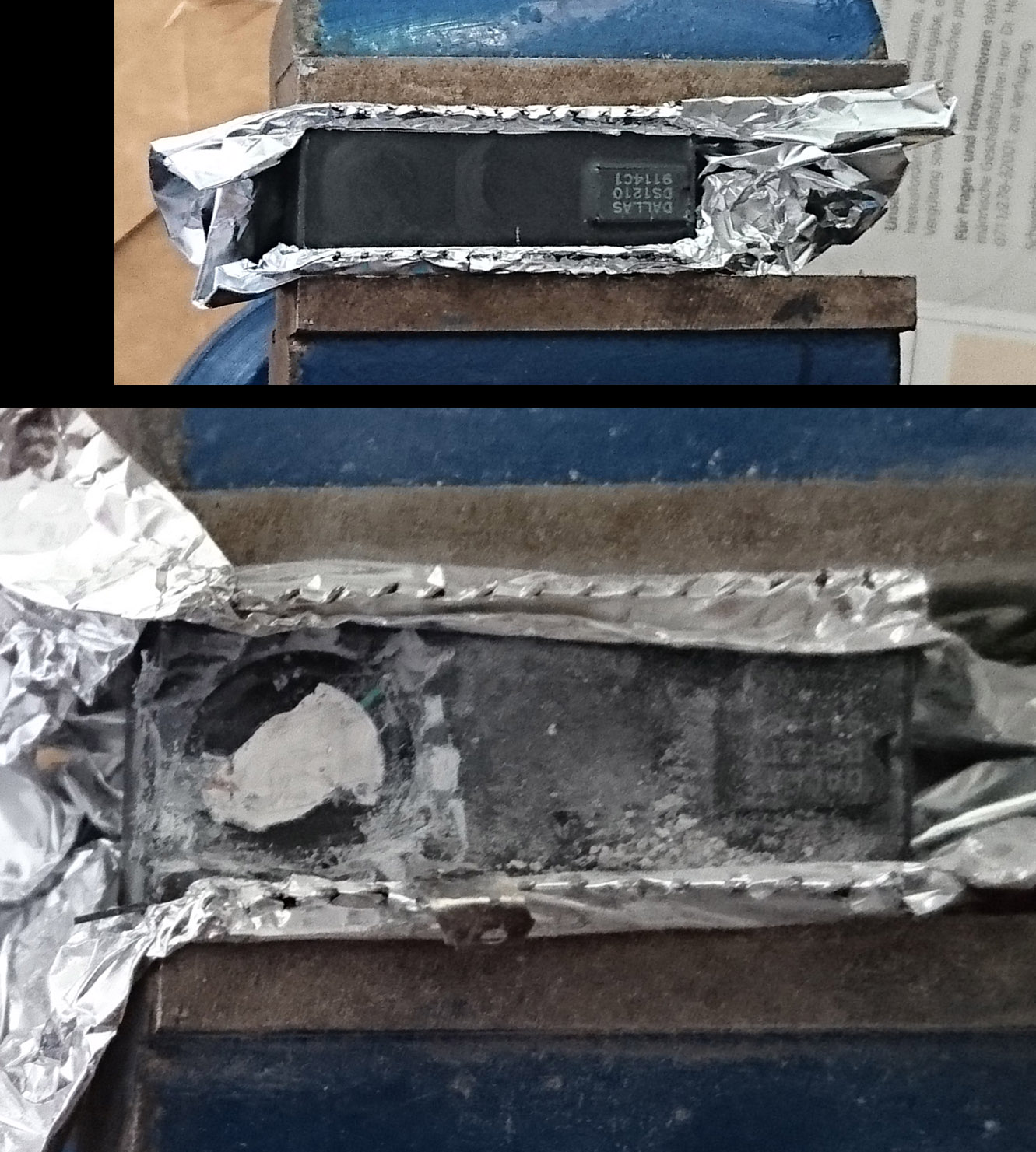
As suspected, it is not this easy. Tektronix replaced the standard print-type Lithium thionyl chloride cells that may be desoldered and replaced easily and only cost a few Euros by SRAMs with an integrated battery. Model: Dallas Semiconductor DS1235BWL-120.
It saved Tektronix a few components, but makes it much more difficult for us: The battery is grouted, you have to either buy a new module for only 45€ at your favorite chip shop or replace the battery. Being a poor student, I desoldered both NVRAMs and searched the battery by trial and error (it resides at the bottom!) and cut it out.
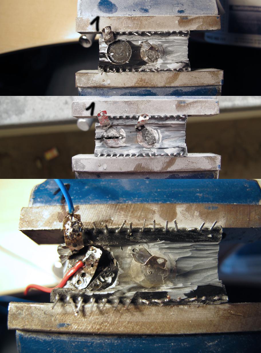
DS1235 teardown
I used a Proxxon tool with the cheapest corunum cutting wheel. The produced dust is fine and should perhaps be filtered.Fixate the NVRAM in a vice, slowly remove the grouting until you hit the left battery and its top soldering tag.There are two batteries, but the left one has fewer grouting that surrounds it.Pay attention to the soldering tag, it must not be cut through!Damaging it requires more grouting removal, thus more work to connect the negative terminal! It is not strictly necessary as it is identical to the NVRAM’s GND pin, but a bit of caution won’t harm.Separate the tag from the battery with a screwdriver and bend it away.Now continue removing the battery by cutting trench into it as the grouting prevents easy removal. Don’t cut too deep, you can destroy the PCB below the battery!Ignore any sparks from a still charged battery.Carefully removing the grouting left (side at pin 1) of the battery aids to judge how deep the battery is when cutting it. And afterwards, the cables run through this groove.Use the trench to grip the battery with a pair of pliers and twist it inside, breaking it free from the grouting. This was the large battery cap.The small cap at the bottom is the positive terminal and is not solderable!Use the groove left of the cap, extend it if necessary (carefully, remember the PCB below!) and lift the cap with a screwdriver from the left.The soldering tag separates from the cap and may now be soldered to the positive supply wire.The second battery remains fully grouted, for future use.Afet soldering both leads is done, clean the module and bend the pins in line, if needed.
Fixing the second module, I cut to deep, of course, hitting the PCB. Only one trace was cut, the negative battery terminal. Therefore you see only on wire leaving this module. The other one got an improvised pin 1 (yellow wire under blue tape) because I started my search for the battery at the top side, not the bottom. And removing the top cover, I accidentally broke it off.
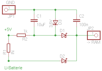
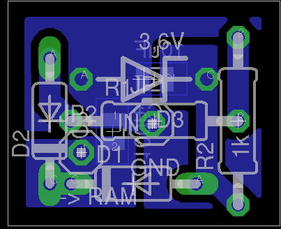
The new battery is installed in a holder, mounted with a screw onto an existing hole in the processing PCB. The small extra PCB contains only two Schottky diodes, a Z diode, resistor and capacitor. The NVRAMs are either supplied by the battery or the power supply, limited to 3.6V.Strangely, the NVRAMs draw more current from the battery when they are powered by the scope and active.I hope to extend the battery life by bypassing it when the scope is running.
The processor PCB has soldering points in the shown area that carry 5V and ground and a point where the scope senses the battery voltage.The modifications of to use the self-powered NVRAMs (see manual changes) are partially reversed so that the scope may sense the battery voltage again.The jumper over the original battery’s place and another jumper (see manual; this re-enables the voltage sensing) is removed.
The circuit is not as nice as it should be, but works like a charm.Well, excluding the cheap sockets that I used for the NVRAMs. I still heard the voice of the Segor shop man, how he exchanged tons of those cheap sockets to the more expensive precision sockets because of reliability problems. Keep that in mind.This prevented the scope from starting at the beginning at all or with strange errors. Bending the NVRAM’s pins solved that (at first).
Battery circuit
corresponding PCB

Processor PCB
Odd behaviour when turning off
A few seconds after the oscilloscope is turned off, the LEDs and the screen flickers. I am sure that this does not extend any circuit’s life, but this problem was postponed.
Some Saturday in August 2011
Errors always occur together
2440 plays possum
It did work yesterday, but today after I switched it on: Nothing happened.
If this was not enough, on the same day, my lab computer and multimeter also stopped working.
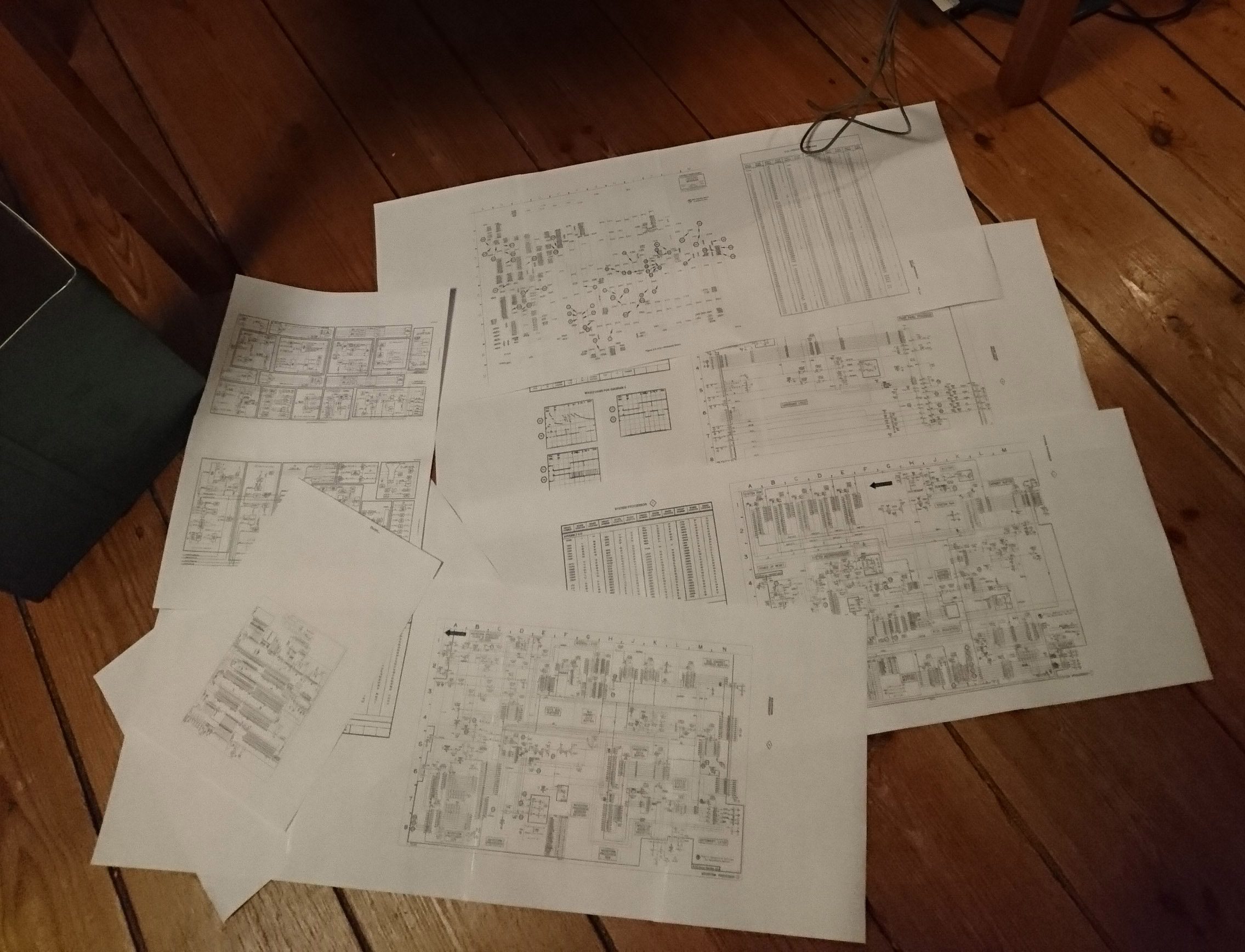
Being at a loss, I read the service manual and traced down possible errors for hours. Unfruitfully, of course.Ignoring severe typos in the manual, everything worked as it should.
It works!
Remembering the Segor guy, pulled the NVRAMs from their sockets and erased them.Whohoo, it works again. So it is either a loose contact or the scope does not boot with a corrupted NVRAM. The corruption could even arise from the turn-off anomaly.
Doesn’t matter, I ripped out the el-cheapo sockets and re-soldered the NVRAMs directly to the PCB. The scope still works.
Power supply
So, since the scope is still taken apart, let’s fix the tun-off anomaly. This really got on my nerves over time.
Removed 10 screws and bolts, the power supply PCB, put it into a holder and connected it to an isolating transformer. Keeping distance to mains-powered circuits and touching them with at most one finger is a good precaution. Measuring, tracing the schematic, colouring it, thinking, measuring, thinking again.
If I am right about the schematic, then there is nothing that prevents the scope from flickering after the turn-off.I may have missed a detail in the schematic that caused the fault in my power supply.
1/4W resistor added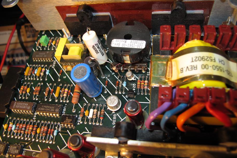
The simplest solution is to add a load to the auxiliary voltage so that the 150 Volts of the buffer caps do not suffice to build up the auxiliary voltage.
So simply solder in a 27kΩ ¼ Watt as described. And then miss the flickering after you turn the scope off.But now, your scope takes three seconds more until it tuns on. There’s no free lunch.
This phenomenon is not special to my scope, it is a “property” of this series,
as somebody of the mikrocontroller.net forum acknowledged.
Bottom line
If you repair something, do it right. Never use those cheap sockets. If an error occurs, fix it immediately.
More pictures
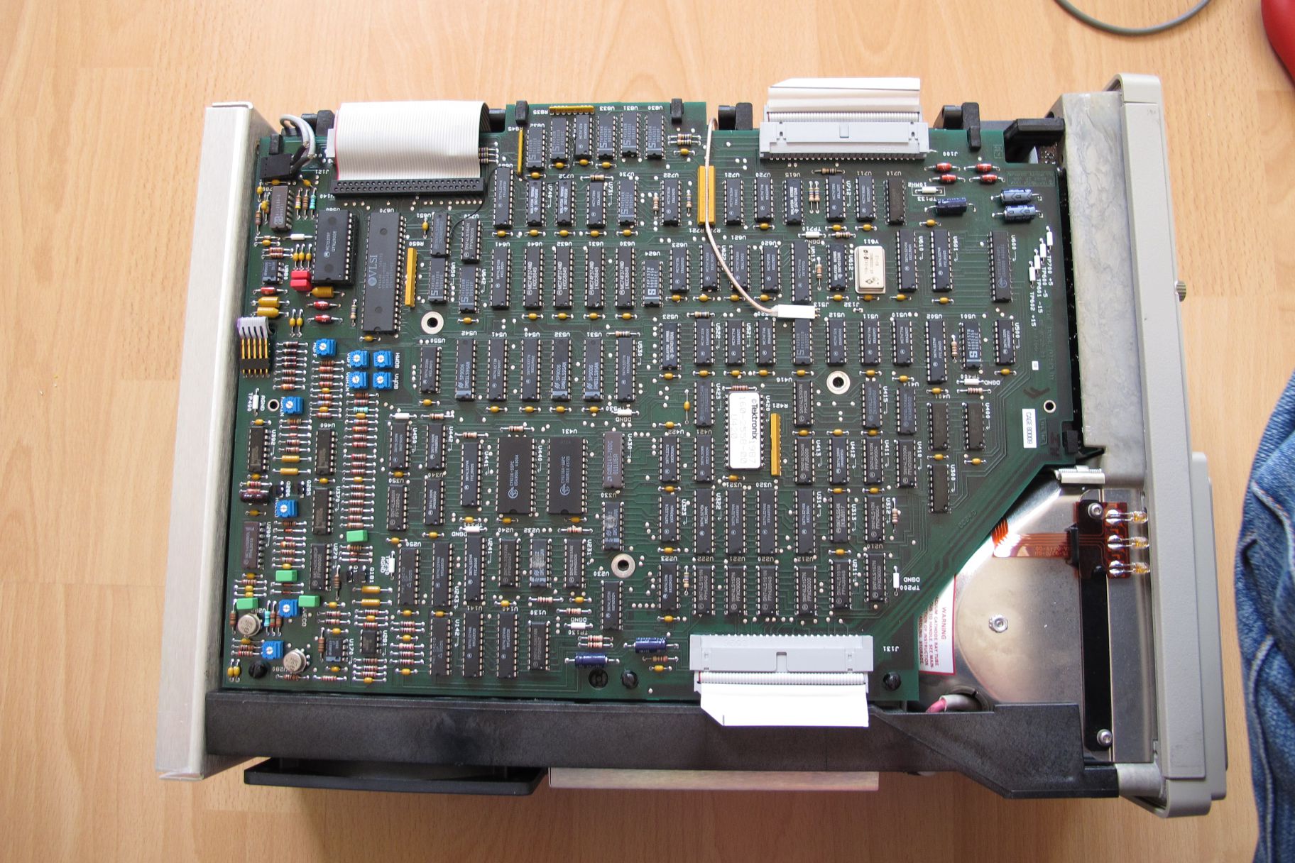
Graphics generation and time base are located on the top side, below resides the processor PCB. The tube is located in the middle inside a steel tube, the power supply is covered by a metal plate. The thin ribbon cable deliveres the graphics signal to the tube amplifier (unseen). The bottom side is dominated by many red Wima-brand capacitors, the gain cells amplifying the CCD signals are to the left bottom. The CCDs themselves are below horizontally-ripped heat sinks and get so hot that you have to cool them actively (done by the fan below the scope). Above reside the peak detectors and the input preampfifiers.So, the signal path is more or less visible.To the top right is the preamplifier for both trigger inputs. Right of the CCDs is the trigger circuit.Below the blue pots for adjusting the CCD clocks is the trigger logic and the CCD clock generation, under black heat sinks.
Top
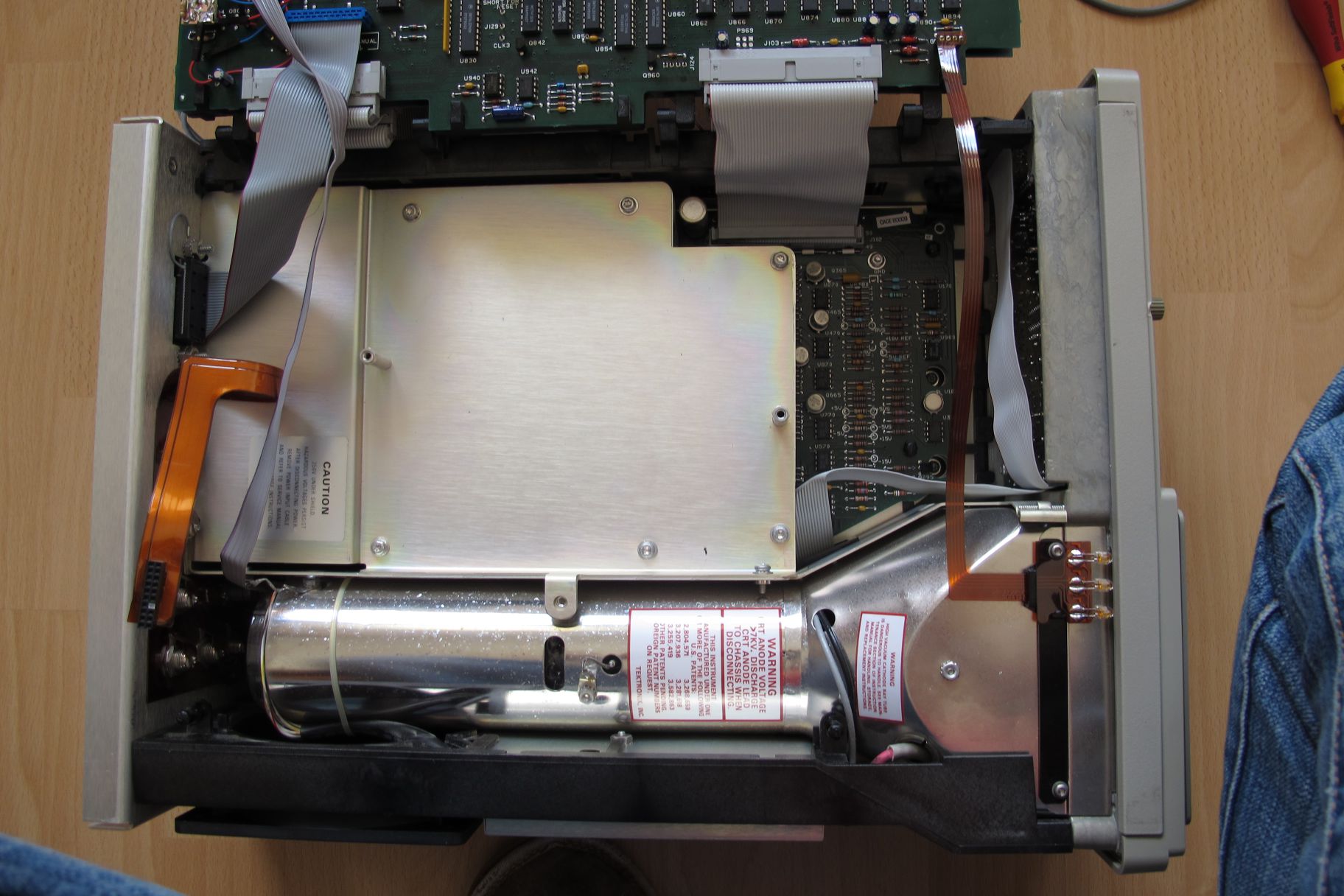
Middle
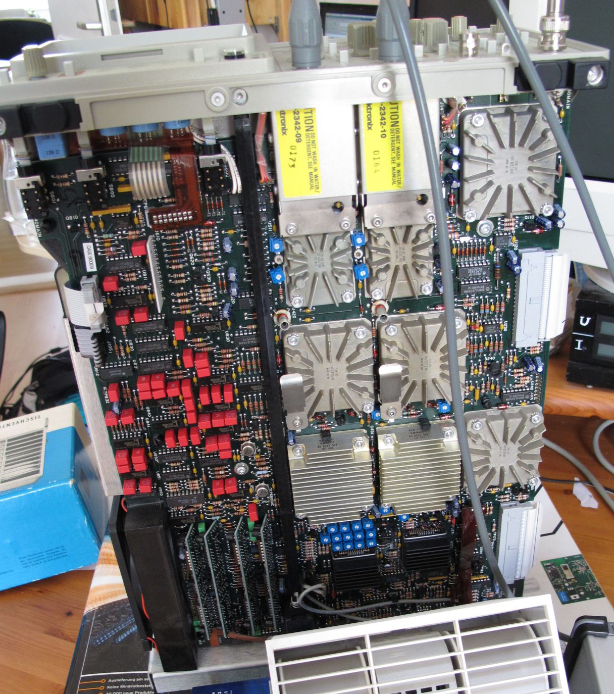
Bottom
2015-01-25: Short circuit
Electronics on strike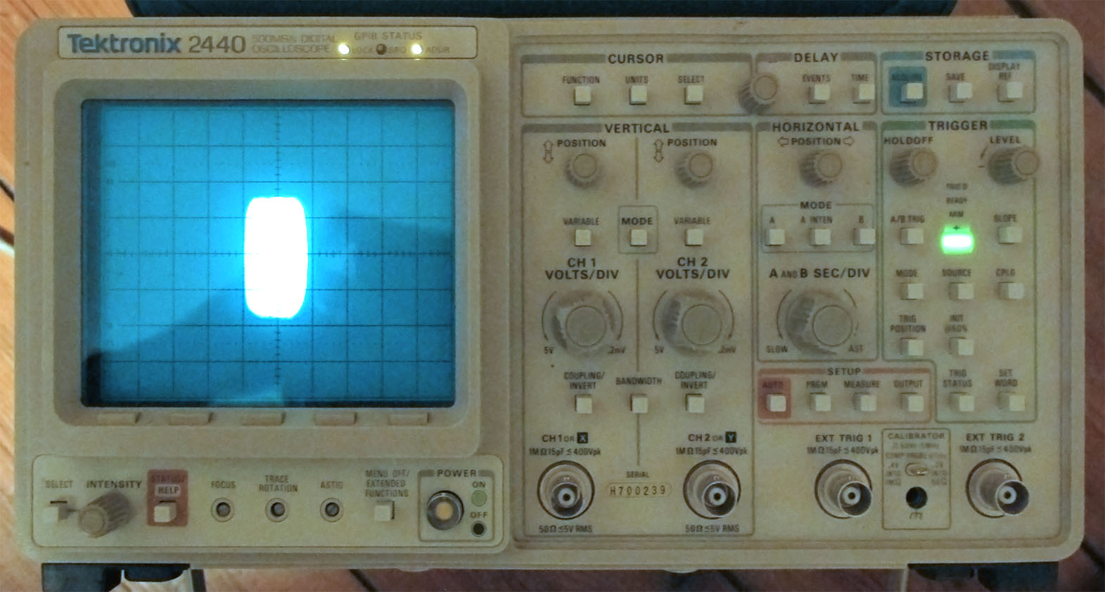
The self-diagnosis at start-up blinks the error code:
2120 DCOK U654
DCOK, so the supply rails might be not OK. This could explain why the picture shrank to a quarter its normal size. At first, I thought the power supply is at fault. All analog voltages were at about ±0.7V. But the power supply seemed to work if I disconnected some PCBs. So it’s not the power supply, right? Indeed, the +15V rail shows a short circuit with < 1Ω resistance on PCB A11 (time base/display output). To locate the device at fault, I connected a power supply to the single, disconnected PCB and drove the faulty rail with 3A at about 1.5V. But nothing got how for a few minutes. So I looked at the service manual, searching for devices connected to this rail. It was only common ICs, easy to get if they were faulty. Still, nothing got warm on the PCB. A look at my power supply showed no current flowing. So, the fault simply disappeared. -.-
It might have been a broken Tantalum cap, a normal electolytic cap or a tin whisker on the PCB. I don’t know, unfortunately. At least, I know where to start searching again if the problem reoccurs.Then, I might check every single cap on the board to pin down the problem.Until now, it suffices to say: The Tek 2440 is alive again—let’s see for how long. ;-)
2017-05-02: Subsequent failures
And so it happened again. The 2440 stayed black. The switching power supply only clicked, but didn’t start up.
Short circuit in 1
The power supply didn’t start up because a positive power rail had a short circuit. With the help of a thermal camera and an external power supply, I could locate the short: It was a Tantalum cap on the time base/display PCB. Unfortunately, I burned the short while locating it. That led to a rise in voltage on that single rail, without the other rails being powered properly. After replacing the broken cap, the 2440 was half dead: It turned on, but didn’t show a trace or run the self test.
Companions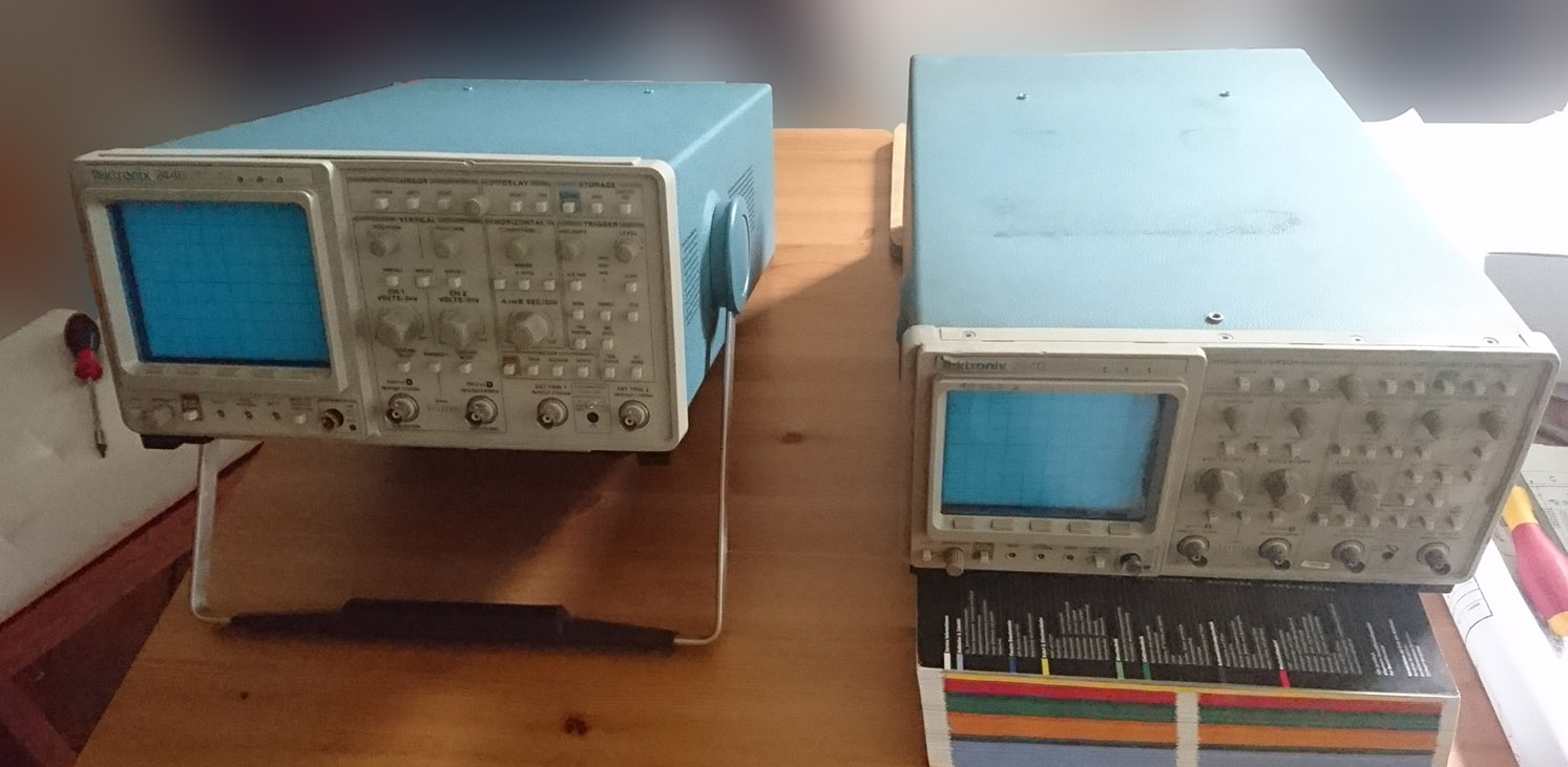
Replacing batteries in 2
What a surprise: Also the second 2440 had dead batteries in the NVRAMs. Apart from that, it seemed to work.
So let’s do it again: Cut open the package, get out a battery and solder some copper leads onto the contacts. Bend the thick leads over and solder a battery connector to it. It’s that easy! Also, it looks much better than my first try.
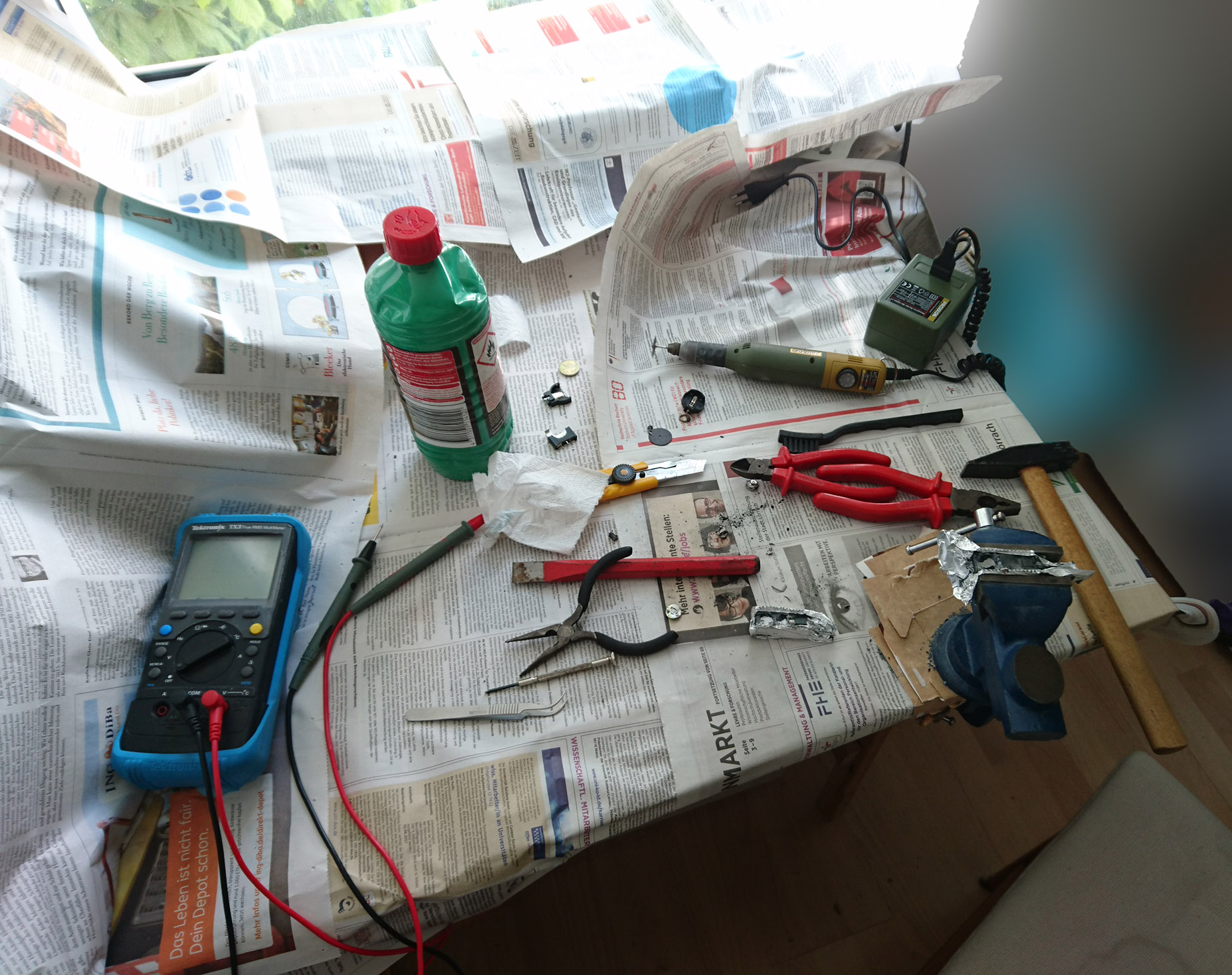
the work space
battery surgery
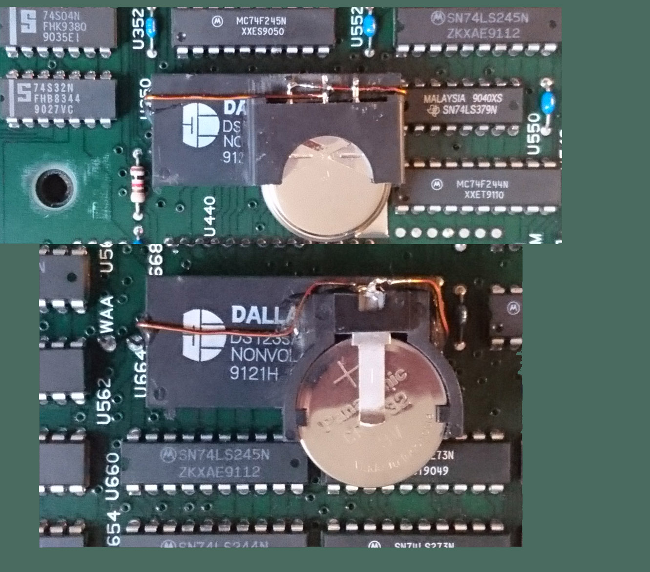
NVRAM, 2017er edition

works again
Calibrating 2
Now it was time to calibrate the second 2440. I took the time to also calibrate the CRT. You can watch all the great features of the vector display that way: Not only its big resolution, but also its capability to solidly fill rectangles on screen. Beautiful!
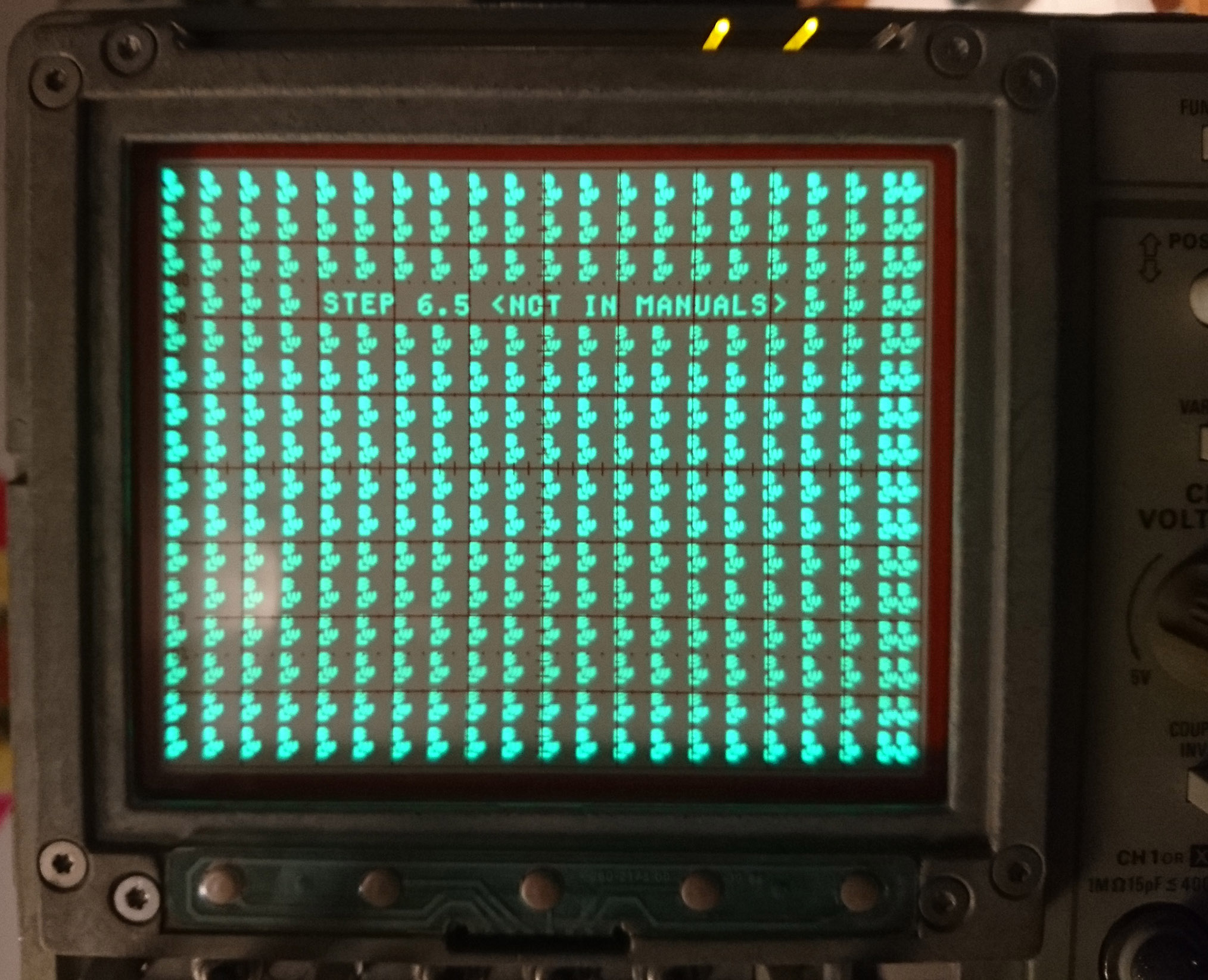
Another step during screen calibration, step 6.5, is not part of the handbook. I don’t know what the pattern is used for, but it’s a nice surprise.
After calibration, the second 2440 works fine.
without frontplate calibration of tube; solid fill easter egg?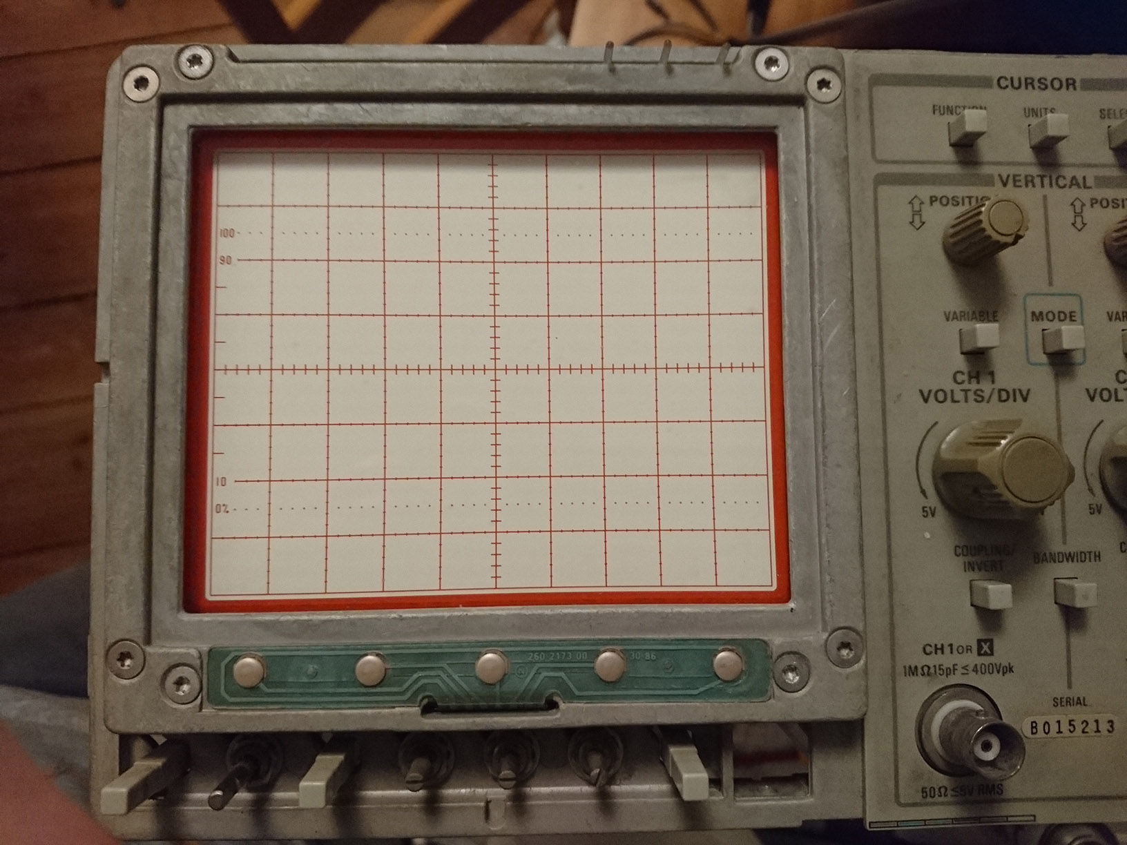
Reviving 1
By exchanging PCBs, I narrowed down the problem to the processor PCB. Measuring further showed that some logic levels were invalid: voltage too low. The Processor also got quite warm and was the only thing that seemed to load those data lines. So I exchanged the CPU and guess what: The scope worked again!
I knew from the start that I grilled something by messing with a power rail to locate the short. That just killed the processor, I learned.
on the hunt for a failure more hunting last failure: CPU