design classic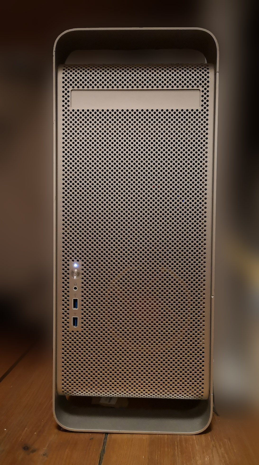
The case is not ATX-compatible. Luckily, The Laser Hive offers conversion kits . I went for the mATX (microATX) kit a 128mm fan. In my case (no pun intended), the ATX power supply is strapped to the bottom and blows its warm air out to the back. I kept the original power connector and used a small cable to connect it to the power supply internally. With the same idea of conserving the original look, I wanted to keep the original front panel, since it’s a crucial part of the design. But USB 3 would have been nice…
Front panel
So the idea was born to convert the front panel from USB 2 and FireWire to USB 3 connectors.
take notes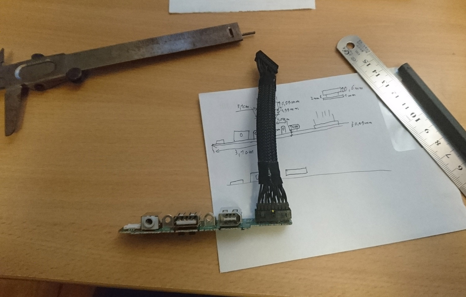
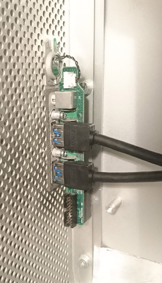
Then, desolder the old connectors. Mark and drill the holes for the new connectors. Roughen the surfaces between PCB and connectors. Check the height of the connectors, adjust it and glue them to the PCB with epoxy resin. While the resin cures, adjust the position again and finally solder the connectors into place, too.
Slightly enlarge he opening of the FireWire port so that it matches the height of a USB port. Also, connect wires for the headphone jack. I didn’t create the circuit to detect the presence of a headphone. But that’s good enough.
Now, connect everything and put the front panel PCB and cover back in place. The result, almost indistinguishable from the original, speaks for itself:
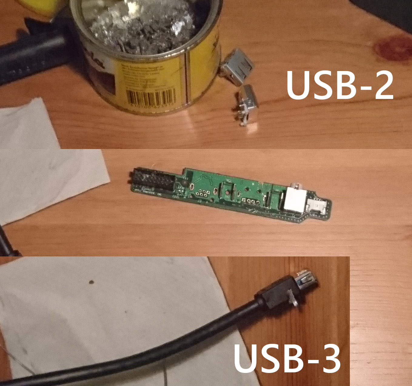
exchange connectors
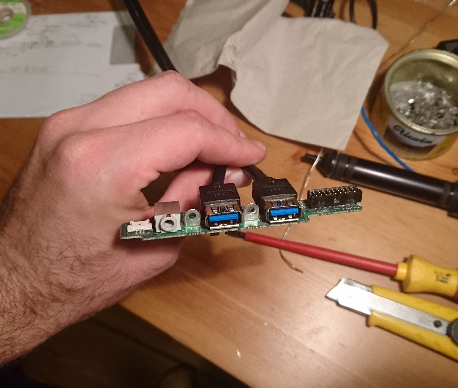
glued and soldered
PCB back in place
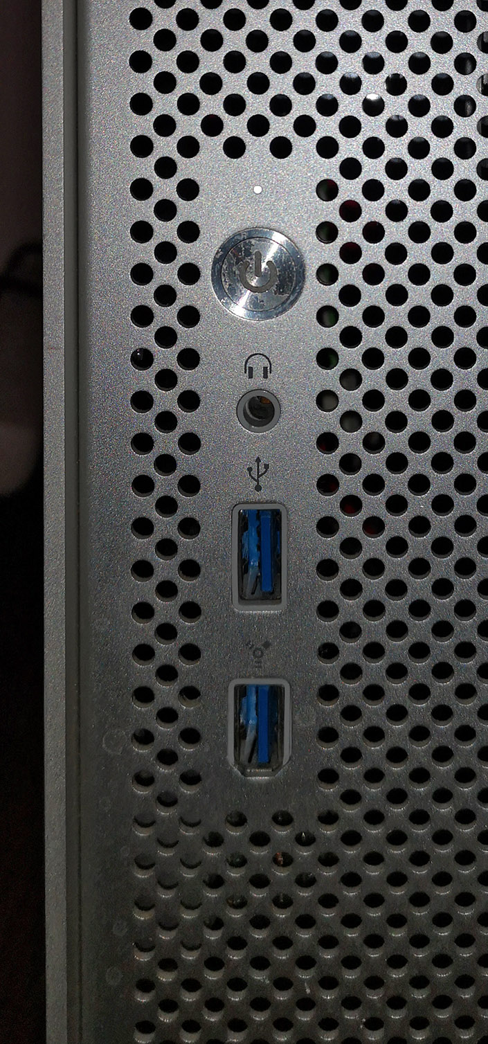
looks almost like before