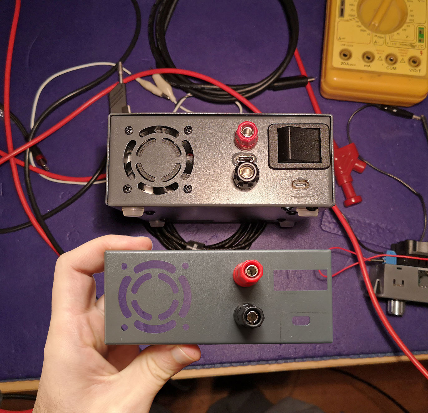
I’m still on my trip to upgrade random devices to USB-C. Thinking about my trusty but heavy bench
power supply (Gossen Konstanter), maybe having a small, lightweight power supply with USB-C would be
a good idea. I mean, the Konstanter is really nice and quiet, but it’s huge. So I gave the
fashionable power supply modules from Hangzhou Ruideng Technology a try. My model, DPH5005, offers
50V/5V on input and output and is a combined buck/boost regulator. Sounds good, doesn’t it? I
ordered it with a case and just had to find a way to equip it with USB-C and USB-PD to source it
from my 45 Watts power bank.
Power supply module
With the DPH5005, you get a solid piece of kit for little money! Its fan only turns on under heavy
load and they even added reverse polarity protection on the inputs. If the output is also equipped
with this protection, I didn’t check. The kit comes in a fancy packaging and when I unpacked it, I
felt an urge to travel to Shenzhen, this Mecca of contemporary electronics.
Just a few minutes after really falling into love with this kit, I looked closer and the picture
got a bit stained:
metal case
The kit comes with a pretty coated metal case. Yet the case is neither grounded nor connected to
any fixed potential. Or maybe it is, if you connect the power supply to your computer via micro
USB and the micro USB jack luckily touches the case. But that’s all hit or miss.
Considering the circumstances, I would have actually preferred a plastic case.
Negative ≠ Negative
The average user would maybe assume that the negative input and the negative output are the same,
a kind of ground, and that only the positive side is regulated. That’s not the case: It is common
practise in power supplies to measure the current with a low-side shunt, in the negative rail.
This means that if you directly connect the negative input and output, you’ll see the current on
the display drop to almost zero. That’s a bit annoying because it means that I can’t connect any
potential to the chassis. If I want to introduce a ground potential, I have to do it separately.
Also, it means that the power source that’s powering the power supply must not be referenced to
your target circuit in any way.
That’s just one reason more for why I wanted to feed the power supply with a power bank…
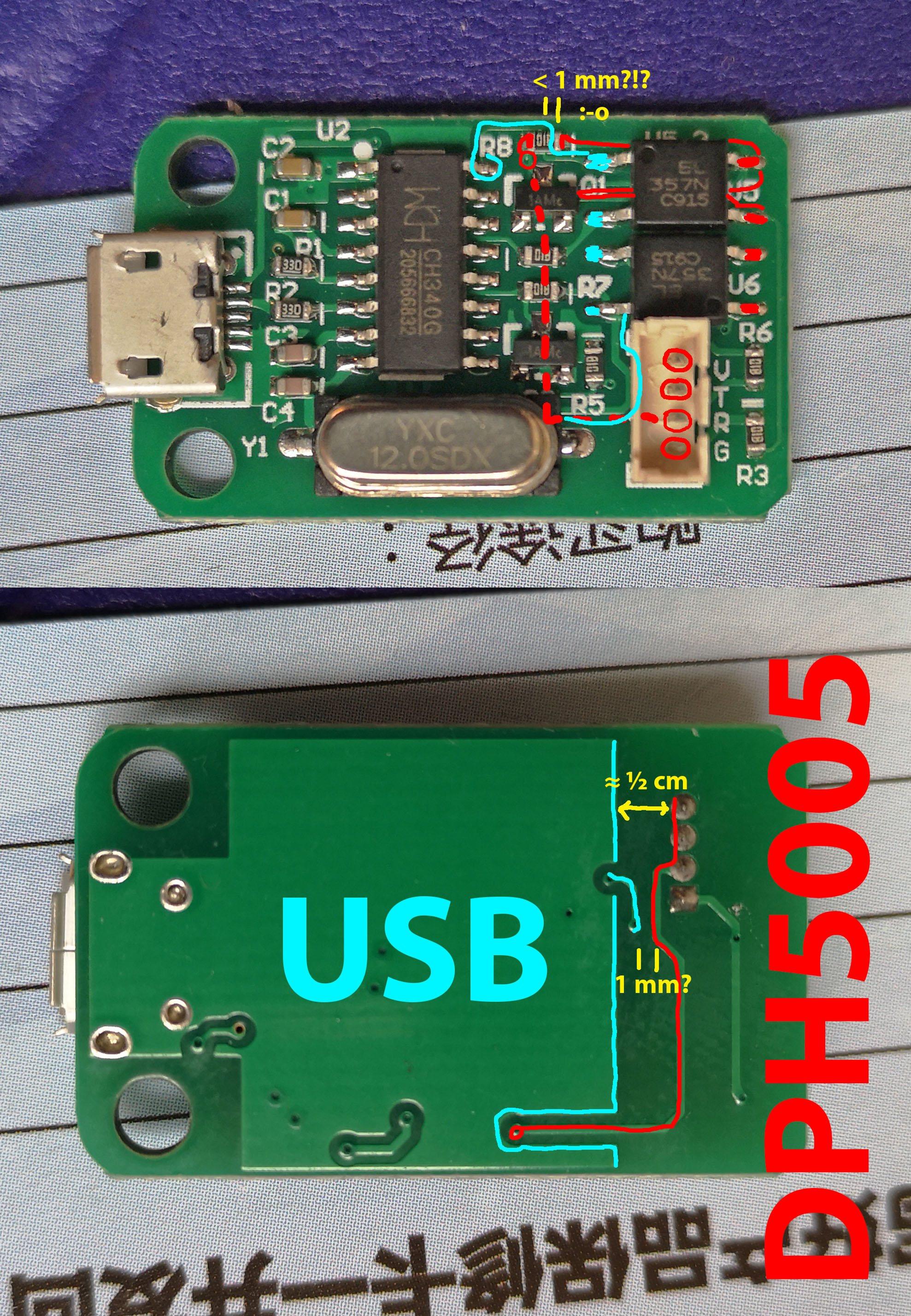
Galvanic isolation for USB: little clearance
Clearances on USB PCB
As mentioned before, the power supply must not be inadvertently connected to other potentials.
This is also true for the USB connection which is why the USB board isolates the USB side from the
rest with two optocouplers. That’s a good idea. But the clearance between both side is just a
fraction of a millimeter at the tightest spot. That’s probably enough for a few kilovolts,
especially since the parts in question are coated with solder resist. Nonetheless, this shows just
how many compromises have been struck in this power supply to meet the low price.
Slow display updates
It’s 2019. I turn the knob, the display updates with 4 Hz.
Two fans
The case comes with another fan that is running all the time. This is in addition to the fan
mounted to the power supply PCB. I would have wished for what I do in my modifications: Build an
air duct and use a single, regulated fan.
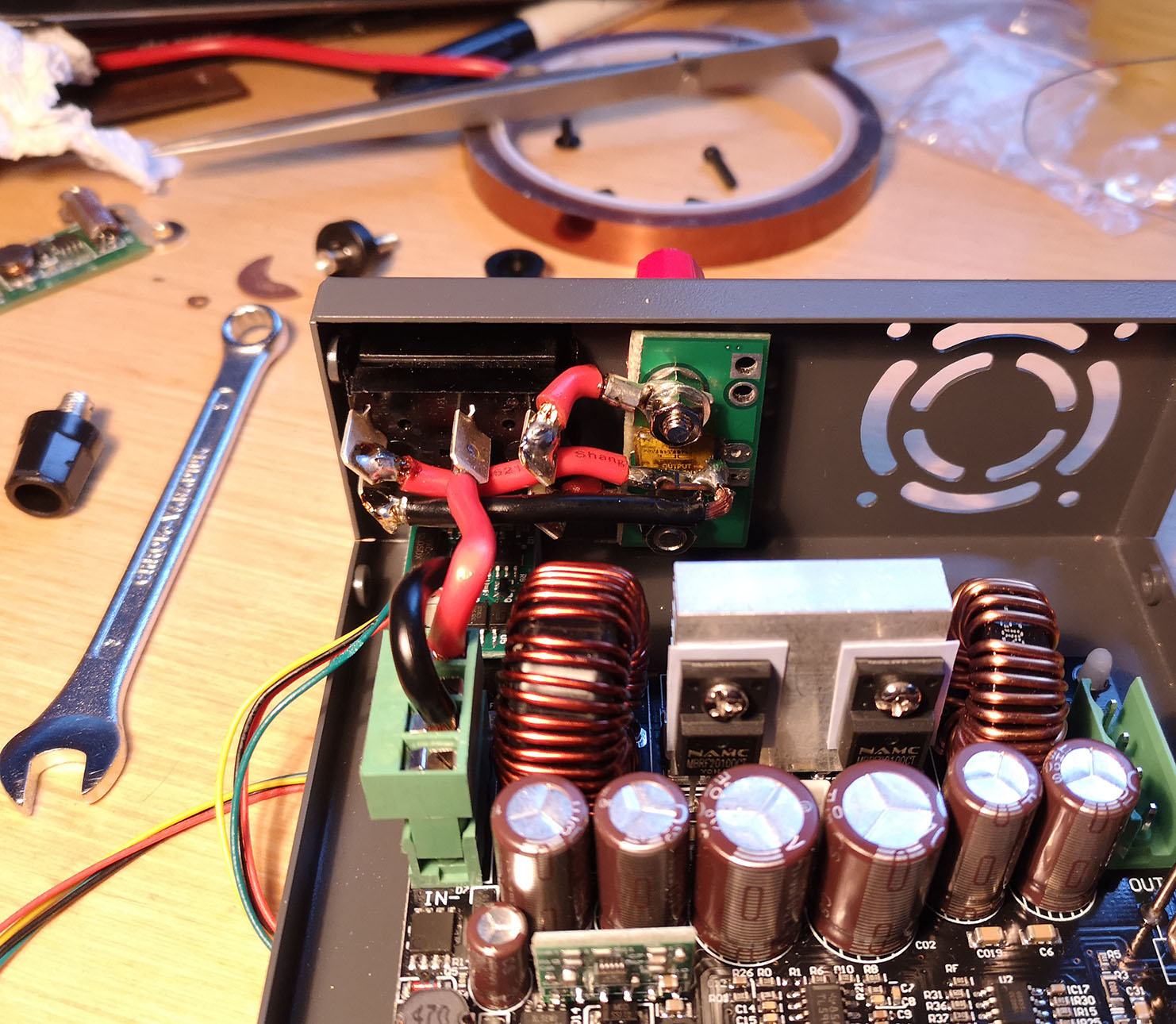
Modifications
Overview
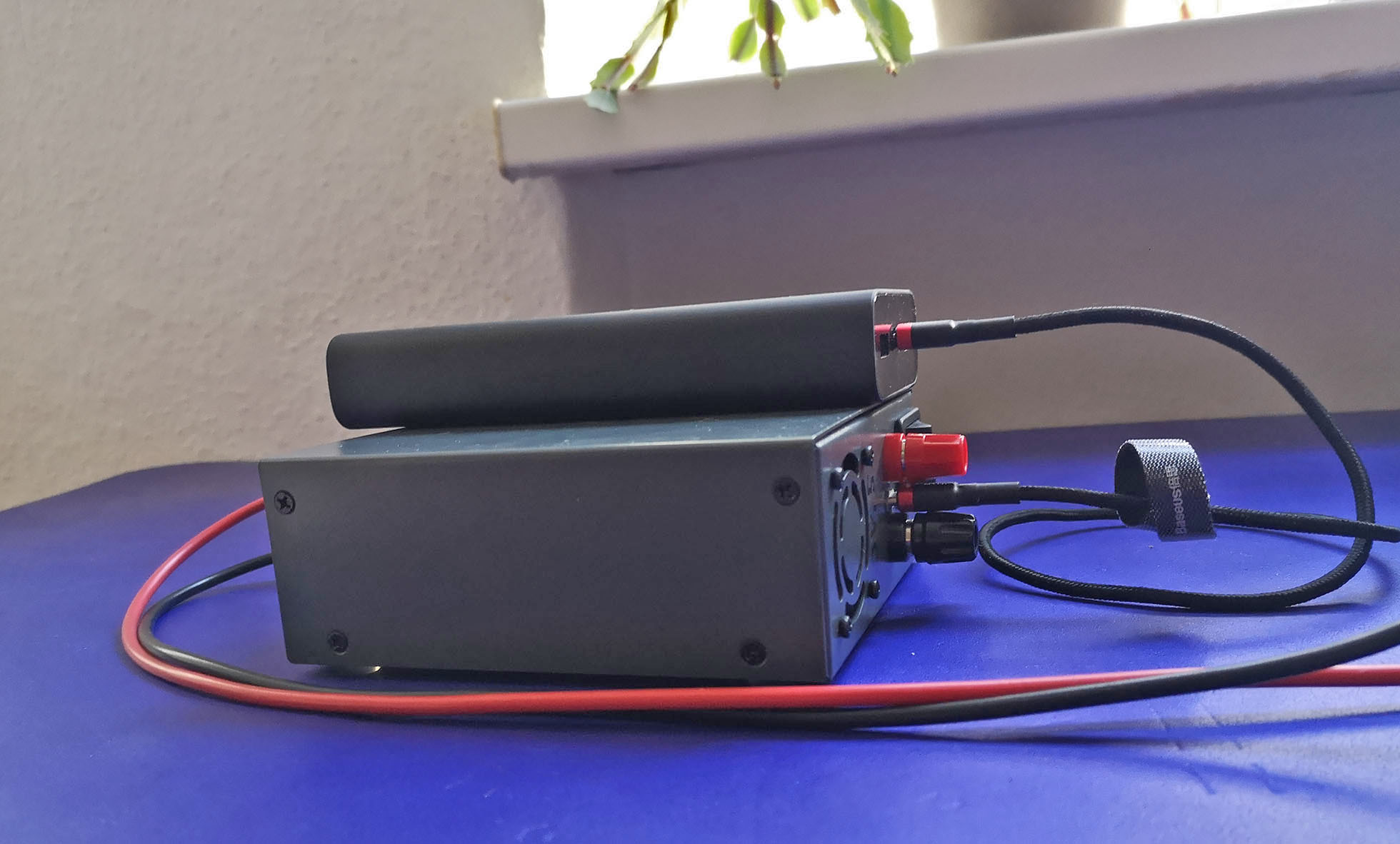
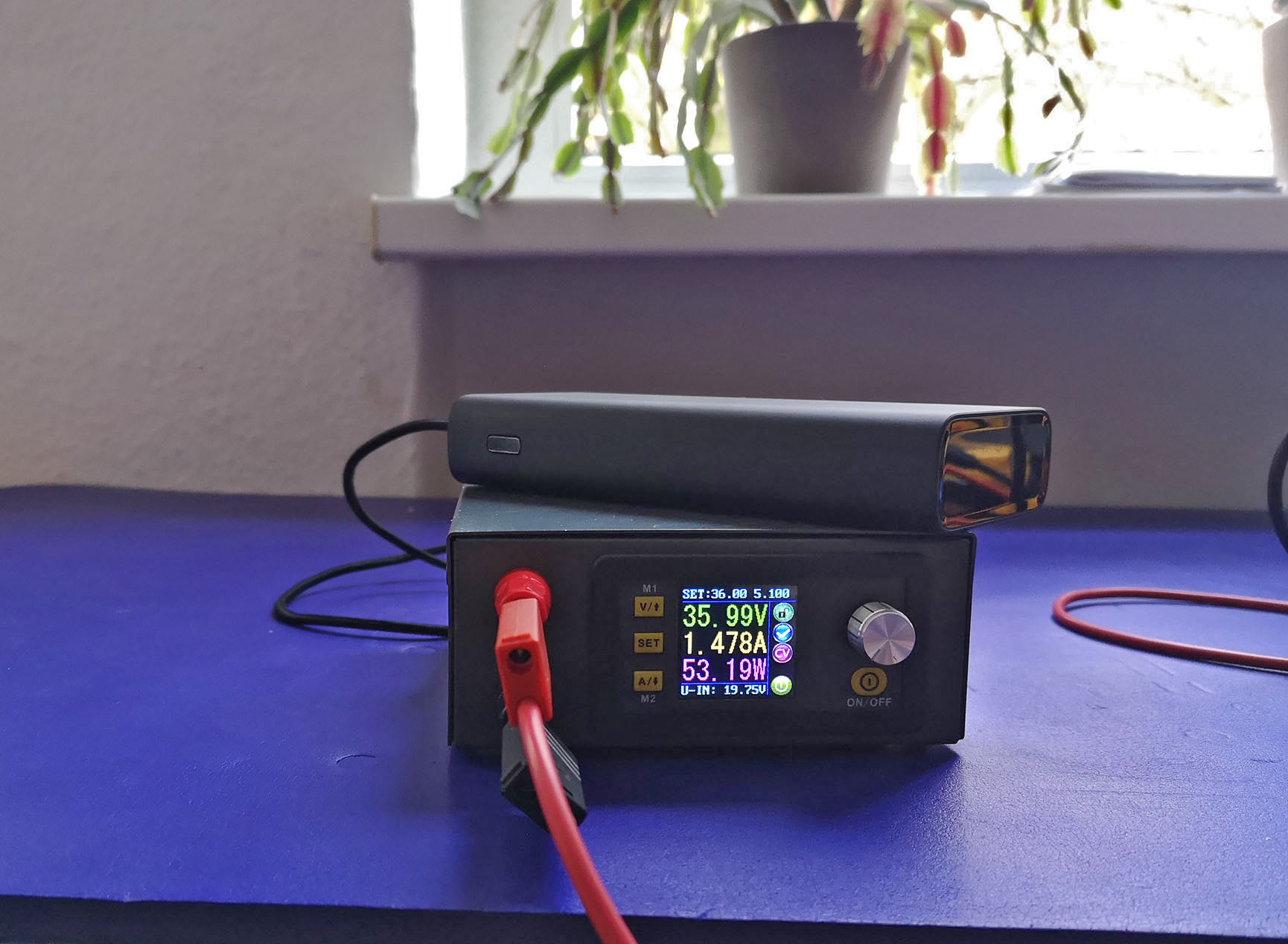
Instead of just assembling the kit, I decided to modify: I wanted to have an additional input with
USB-C/USB-PD to use the power supply on the go, Depending on the power bank, you can source 45 Watt or
65 Watt. Also, I do not tolerate devices with loud fans on my desk — unless the gear is older than
me (hello, trusty Tektronix 2440).
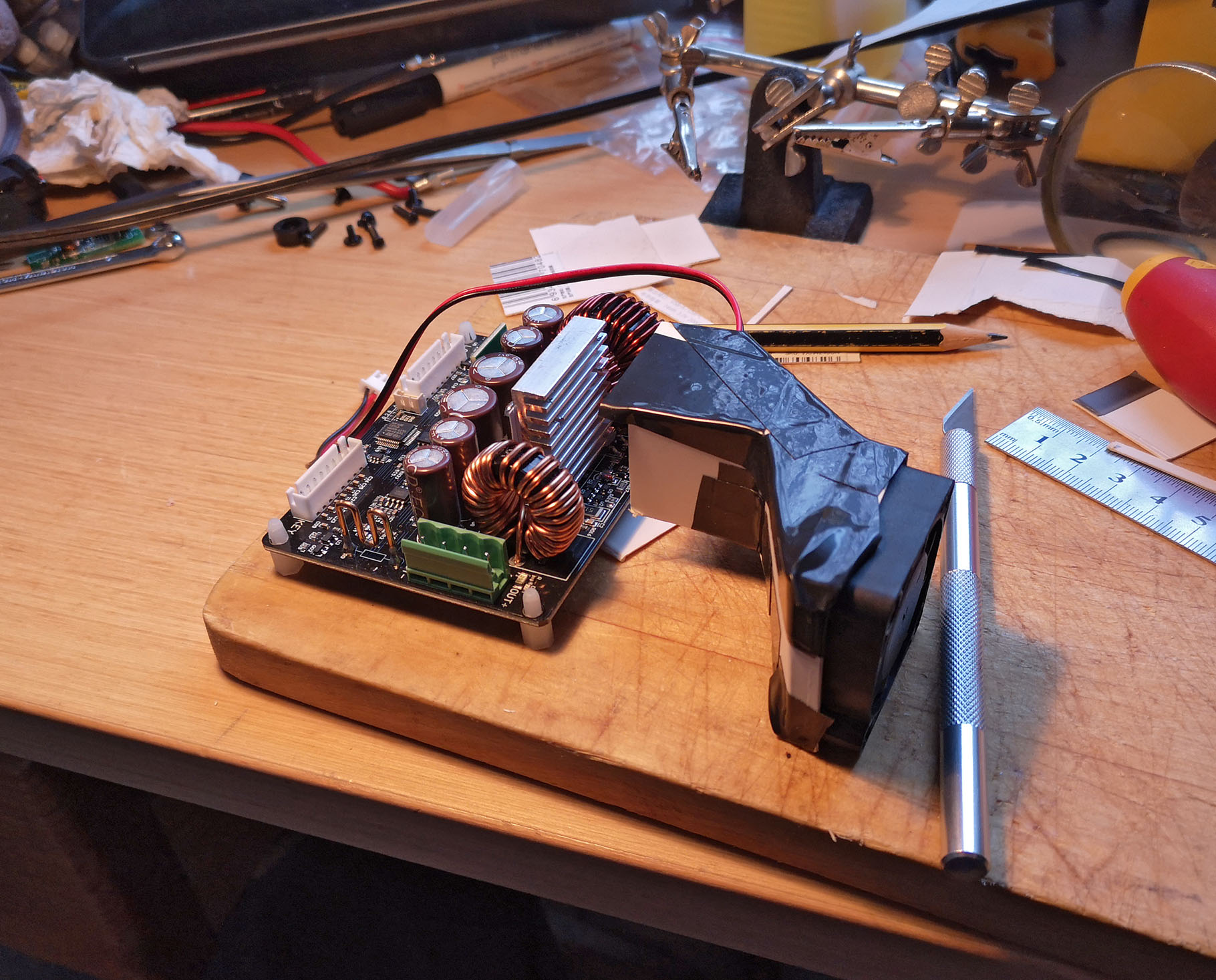
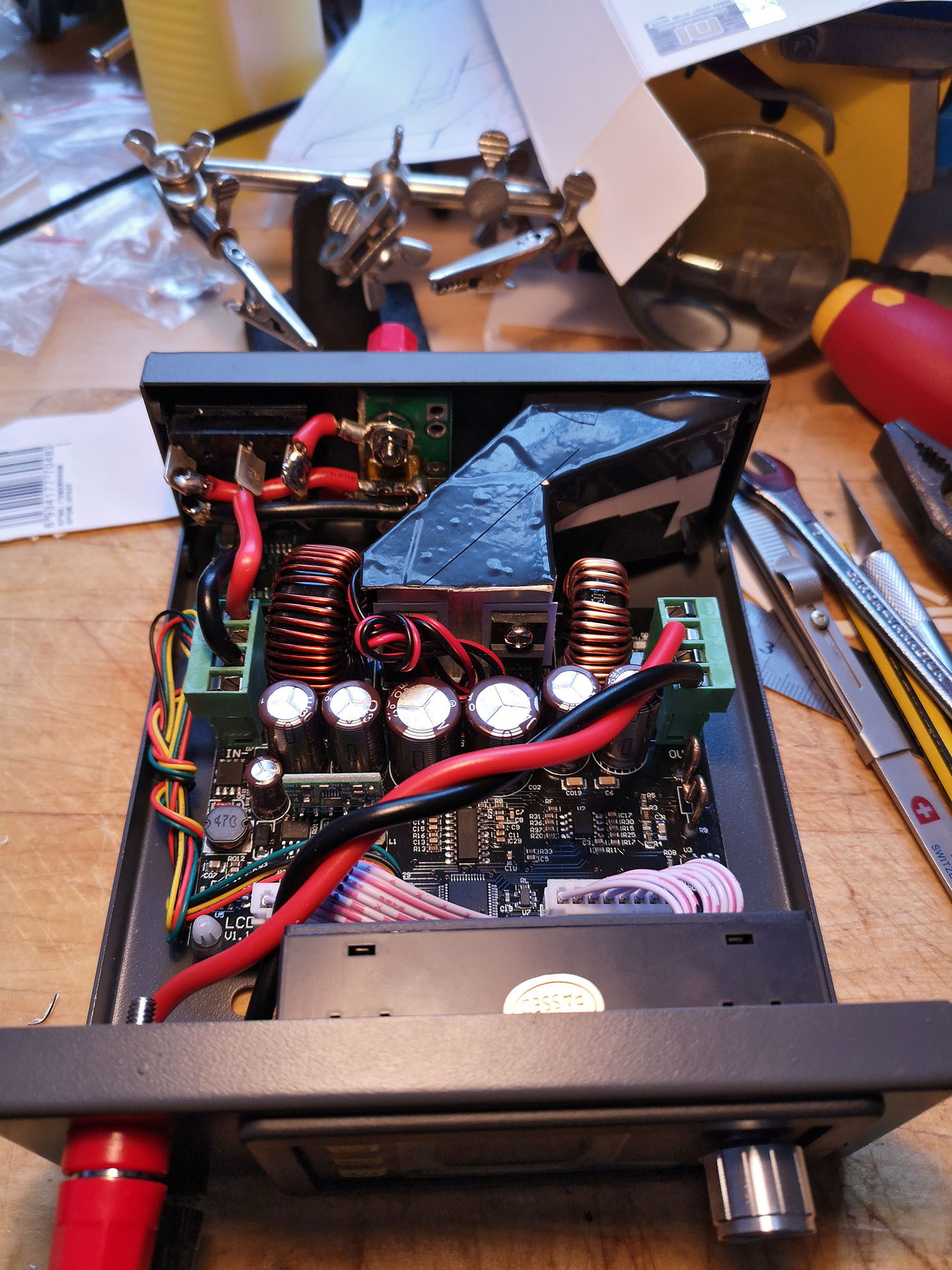
One fan, one duct
Air duct
It’s a good coincidence that both fans use 5 Volt and have the same connector. What’s left to do to
remove one of the two fans is to build a duct that guides the air from the fan on the case to the
heat sink on the PCB. I made it from card board from the packaging of my Xiaomi power bank and tape.
The cross section of the duct changes along the way in both dimensions, getting narrower to avoid
coils and jacks along the way. The duct is flush with the heat sink on one side and open on the
other side to let the air escape in that direction. I hope that this is good enough, but I still
have to measure temperatures.
Galvanically isolated case, USB-C/USB-PD
To ensure that the case is isolated from the shielding of the micro USB jack, I wrapped it in Kapton
tape and held it securely in place with epoxy glue. That way, the Kapton tape can’t move and or be
cut by the case, which would destroy the isolation. The tape itself is also necessary to stop the
epoxy from seeping into the USB jack, which would make it impossible to plug a connector to it.
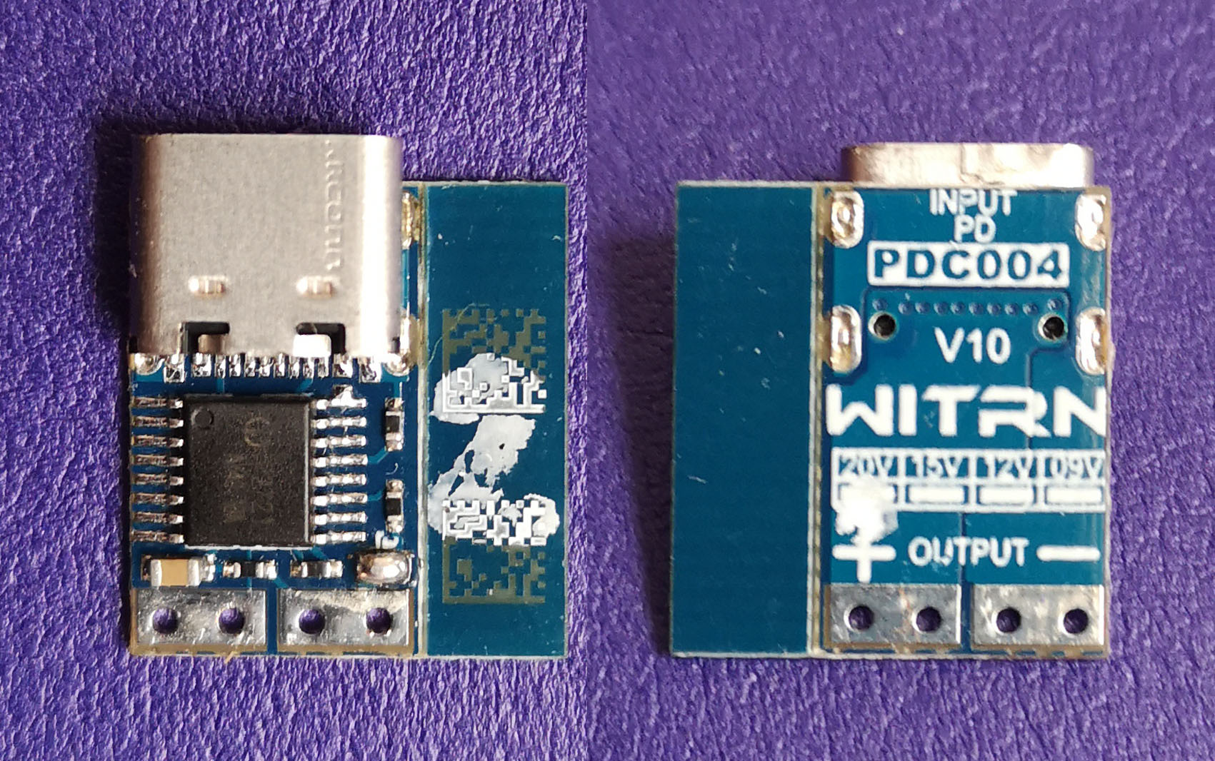
For the USB-C port, I once again used a tiny USB-PD trigger board with USB-C jack that I got via
AliExpress. The board is a USB-PD sink and negotiates 20 Volts. With this jack, it is even more
crucial to isolate the shield, which is connected to the negative side, from the case. As mentioned
above, a failure to do so could lead to a mix of the negative potentials, disturbing the displayed
current.
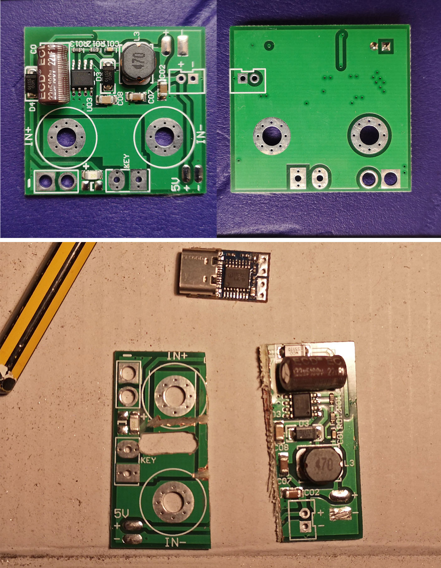
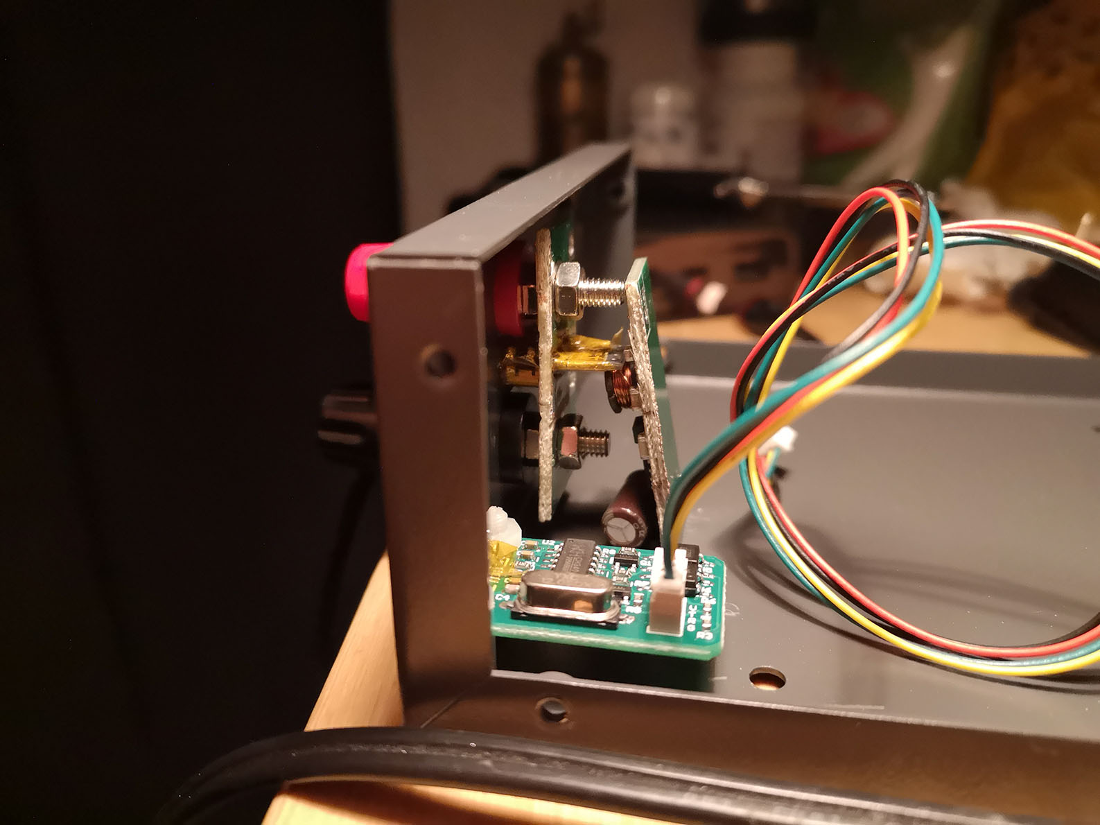
I was lucky to have the now unused 5 Volt regulator board. It makes for an idea holder for the
USB-PD board. Its distance from the case is perfect to keep the USB-C jack in place. On the
regulator board, traces were cut and it was also wrapped in Kapton tape to avoid any connection
between the input jacks and the USB-C jack. The whole setup was also glued in place with epoxy.
Until the epoxy got hard, I had to keep the USB-PD board perpendicular to the back side of the case
with the help of the remains of the regulator PCB. :D If not, the USB-C jack would have been put at
an angle, which would make the USB-C cables stick out at an angle, too. I think that would have
looked odd.
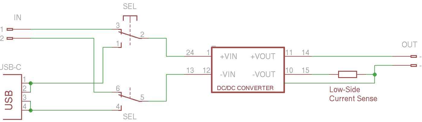
Both inputs are selected with a 2-sided switch. It should prevent expensive mistakes if something is
connected to both inputs and they share some potential. To use the new switch, I had to enlarge the
cut in the case significantly.