Thermometer and sensor
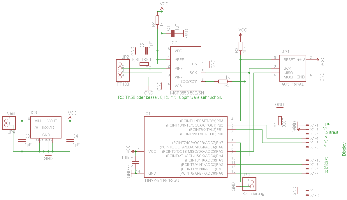
Schematic
I built a small thermometer based on Microchip’s AN1154, which uses the famous MCP2550. Please refer to the application note for details on how the measurement is done.
The beauty of the thermometer is the big resolution of 0.01 °C over a wide temperature range. The accuracy won’t be above 0.1°C, but well. I also don’t have the means to check the precision of relative measurements, so I have to trust the application note on that. The given temperature range of -80°C to 600 °C is huge, but you shouldn’t expect miracles. Accuracy won’t be great across that huge range of temperatures.
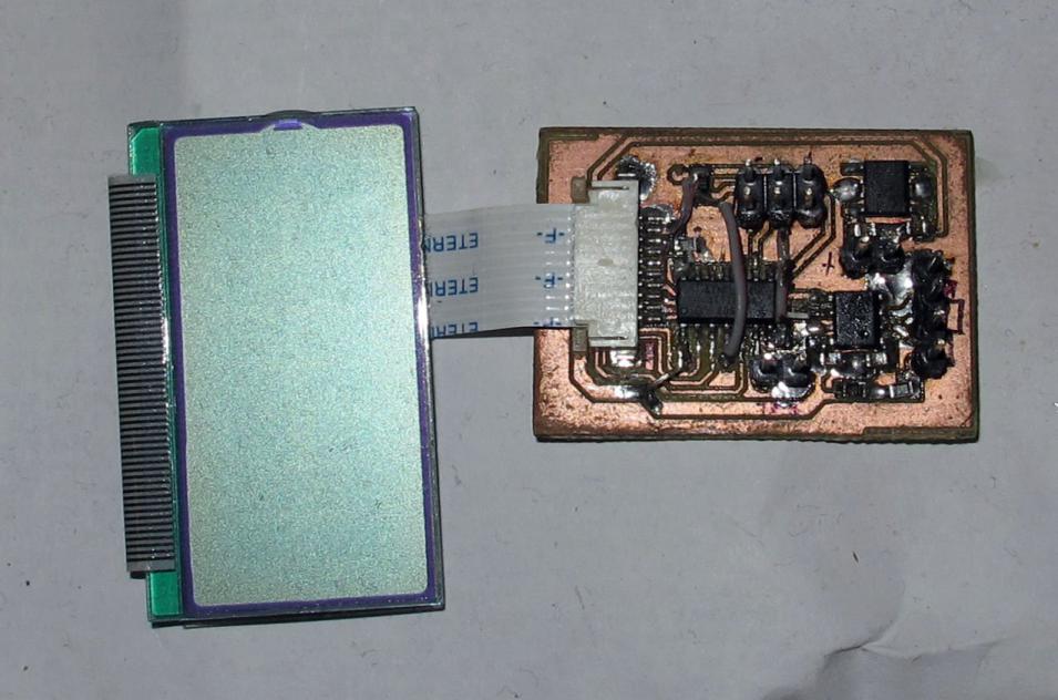
On the plus side, the thermometer is cheap and easy to build. I got the LCD (0.95 €) plus connector from Pollin and all the other parts from Reichelt. Oh, please don’t forget to order a Pt100 sensor! ;) For best accuracy and precision, the reference resistor is very important: It should have a very small temperature coefficient. Its absolute value is of less importance, since that will be solved by calibration. Unfortunately, I didn’t get such a resistor at Reichelt. :< So my measurements will be off a bit when the ambient temperature changes.
The MCP2550 uses ratiometric measurement to determine the resistance of the Pt100 sensor. The AVR processes the raw measurements, taking the Pt100 resistance curve into consideration and sends the result to the LCD and (2019, new:) via UART over the calibration pin. The Pt100 resistance is determined via a 4-terminal measurements. Better be on the safe side. ;) I milled the PCB one-sided, which neccessitated some wire jumpers. There is also an ISP header to program the device and pins for the supply voltage and a jumper connector to trigger calibration. That jumper connector is also the serial outut. A resistor limits the current, to be on the safe side.
The temperature is sent with 9600 baud through the serial interface. A cheap USB/Serial interface makes it accessible from the computer.
Measurement
im Betrieb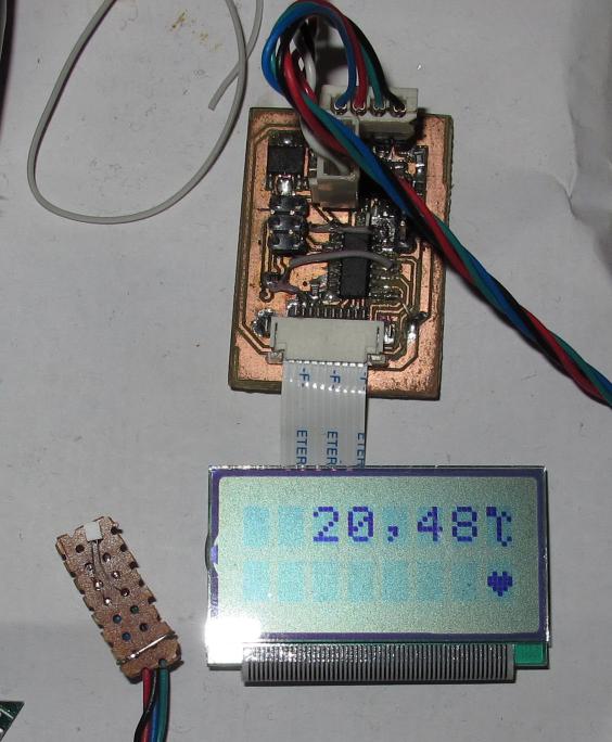
Blue thermal isolation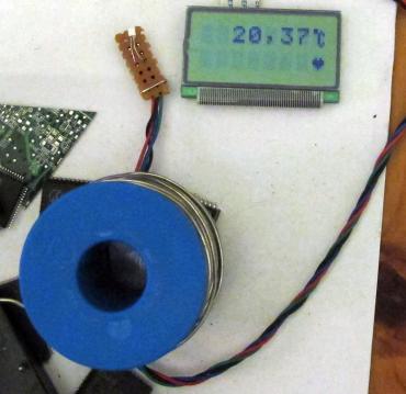
Calibration
Calibration with trim pot
The calibration temperature is fixed to 0 °C. This means that the ideal Pt100 element is expected to have a resistance of exactly 100 Ω. The actual measured resistance is used to determine the value of the reference resistor so that the displayed temperature will effectively be 0 °C. Once the user is satisfied with the displayed result, removing the calibration jumper will write the calibration value to EEPROM.
Just, how do you get 0 °C precisely? Well, you don’t. ;) But I have a high-resolution multimeter and a 10-turn pot with 200 Ω that I manually trimmed to exactly 100.05 Ω – I couldn’t get closer by turning it with my fingers. Then I soldered the pot to the 4 wires, let it get cold again, did the calibration and swapped the pot with the sensor. Calibration done.
The heart
The observant reader will have noticed that there is a heart on the LCD. It’s not a symbol of love, but a symbol of life. It’s an hommage to the old HP Apollo workstations. They also had an LED that pulsated like a heartbeat. Later editions had the heart as part of their status LCD: bup, bup, –, bup, bup, –, …
It was a nice way of showing that your computer is still alive. The same here: The pulsating heart shows you that the device is continuously acquiring temperature measurements and didn’t freeze up.
Apart from that, the heart also allowed me to test the use of custom symbols in the LCD library. :D
Files
New (2019): Version 1.2 of the Software outputs every displayed temperature reading also via a software UART on the calibration pin (A7). It just takes a cheap USB/Serial converter to supply the thermometer with 5 Volts, bypassing the voltage regulator, and you now got a USB termometer!
The schematic and PCB in Eagle format as well as the software is available under a BSD license:
| Files |
|---|
| minipt100-r20191112.tar.bz2 |